Isolated Power Systems Equipment
“isolated power systems equipment rated 600 Vac or less”UL Standards & Engagement · OFFICIAL SOURCE↗

 CB / 03
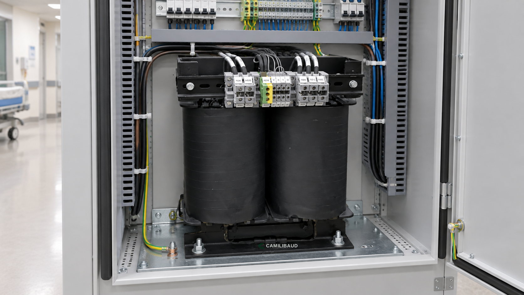
Medical isolation transformer · CAMILIBAUD
MODEL FAMILY CB-IPS-05
Isolation transformer options coordinated with the patient-area load and panel design.
CareLine IT is the transformer family within the isolated power system. Capacity, voltage arrangement, thermal monitoring, mounting and enclosure are coordinated as one engineered assembly rather than selected from a room name alone.
SYSTEM ROLE
The transformer provides galvanic separation for the designated isolated circuit. Its rating and arrangement depend on the connected load, supply, temperature rise, ventilation, installation environment and applicable project requirements.
Show the transformer in the panel or equipment room serving the designated area. Keep the isolated distribution boundary clear on the one-line diagram and coordinate the monitor, protective devices and alarm interfaces around it.
ENGINEERING DATA
Explore the system application, monitored functions, interfaces and project inputs for this product family.
| Rated power range | 3.15–10 kVA class |
|---|---|
| Nominal system | 120 V class secondary; primary arrangement per approved model |
| Frequency | 60 Hz for the North American application shown |
| Thermal design | Temperature monitoring and free-air / enclosure requirements by model |
| Installation | Open-frame or housed assembly; mounting and protection per submittal |
OFFICIAL STANDARD EXTRACTS
“isolated power systems equipment rated 600 Vac or less”UL Standards & Engagement · OFFICIAL SOURCE↗
BEFORE SPECIFICATION
Bring the answers into the one-line diagram, equipment schedule and alarm plan.