Uninterruptible Power Systems
“continuity of an alternating power source”UL Standards & Engagement · OFFICIAL SOURCE↗

 CB / 04
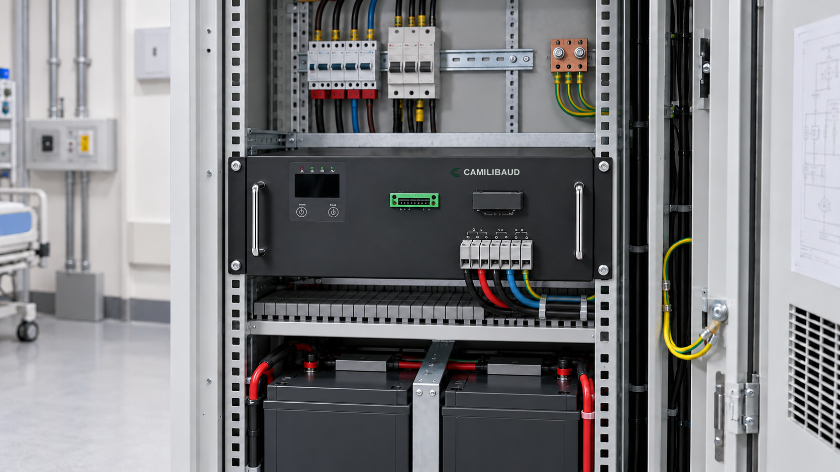
Uninterruptible power · CAMILIBAUD
MODEL FAMILY CB-UPS-03
A separate backup-power layer sized for the loads identified by the project.
Continuity UPS is planned around a defined load list, required ride-through and maintenance strategy. It is treated as a distinct power branch so the design team can state exactly which systems receive UPS support.
SYSTEM ROLE
An uninterruptible power supply supports selected loads during a supply disturbance according to its topology and battery configuration. It should not be assumed to sit in series with every isolated patient-area circuit.
Coordinate the UPS and battery arrangement with the selected loads, electrical room, ventilation, bypass strategy, maintenance access and alarm destination. Show the supported circuits explicitly in project documents.
ENGINEERING DATA
Explore the system application, monitored functions, interfaces and project inputs for this product family.
| Rated power range | 3–10 kVA class |
|---|---|
| Topology | Online double-conversion |
| Autonomy | Calculated from the critical load and battery configuration |
| Bypass and service | Maintenance and isolation approach defined by design |
| Project inputs | Load profile, starting current, runtime, room and battery plan |
OFFICIAL STANDARD EXTRACTS
“continuity of an alternating power source”UL Standards & Engagement · OFFICIAL SOURCE↗
BEFORE SPECIFICATION
Bring the answers into the one-line diagram, equipment schedule and alarm plan.